 A key part of ST-2110 vs SDI is that video/audio/ancillary streams are separated. But how are they synchronised when receiving? Timestamps play a vital role in this synchronisation process, but there is a major lack of understanding in the industry about them. We have written our own 100 Gigabit ST-2110 implementation in our low-latency encoders and decoders and so have a deep understanding of the technical details. (Note that we’re referring to timestamps and not timecode in this blog post)
In a previous blog post, we discussed how ST-2110 works at a basic level. In this blog post, we’ll dive deeper into the details of timestamps in ST-2110 – and how to avoid the very common confusion between packet arrival time and timestamps. This post is quite technical!
But first, a quick recap.
Why Do We Need Timestamps?
 In ST-2110, video is chopped up into thousands of little images known as “packets” that are then sent to a receiver. As its name suggests, the receiver receives the packets – not necessarily in the right order – and must then put them back into sequence.
Exactly the same thing happens to audio – except it is chopped up into thousands of tiny sounds (instead of images). These packets must also be sequenced correctly – and connected to the corresponding image packet, so that the sound of someone kicking a ball occurs when the viewers see the ball being kicked.
So how do you sequence the packets and connect each audio packet to the corresponding video packet? By using timestamps.
Timestamps provide timing information about when a specific piece of media should be presented.
The Role of PTP
The problem with timing in ST-2110 is: how to keep timing consistent across devices using different clocks? This is important, for example. when recording the same event from multiple angles, to make sure that for example a change in camera angle doesn’t show the same event again.
The solution is to use the Precision Time Protocol (PTP). This is a way of measuring time designed to synchronise all devices in a network, ensuring that they operate on the same clock, both frequency and phase locked. This blog post won’t go into the intricacies of PTP as there is plenty of documentation online about this.
 How does PTP work in ST-2110? This, however, is a topic which is poorly explained online so let’s try and explain it well.
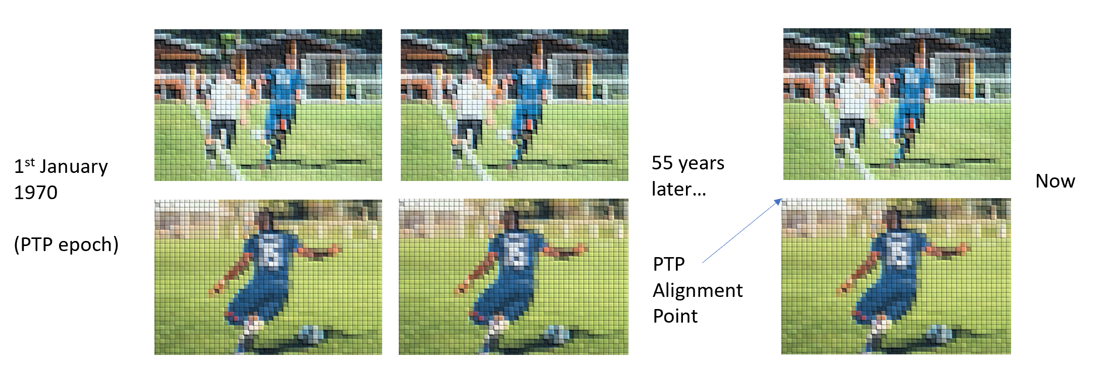
Imagine that all television signals start at the same time on January 1, 1970 (even if they didn’t in reality of course). Each video frame lasts for a certain number of clock ticks (for example 40ms for 1080i25 video). By calculating how many frames have been sent since that time and when the next frame will begin, all senders know when to transmit the next frame and can therefore remain in sync, for both frequency and phase. This is shown in the picture above – the two camera angles remain in sync as their sources are locked to PTP.
Calculating Timestamps
When delivering media, using ST-2110, which uses the Real-Time Protocol (RTP), the timestamp is included in the header of each RTP packet. These timestamps are calculated using a PTP clock and are represented as a 32-bit value. For video, the clock runs at 90kHz, while for audio, it runs at 48kHz.
As mentioned earlier, timestamps are calculated by imagining that time started on January 1, 1970. But because an RTP timestamp value can only be represented with 32 bits, there will come a time when these values reset and start over again. We refer to that as “wrapping around.”
Video timestamps wrap around after about 13 hours (2^32/90000/(6060)), while audio timestamps wrap after about 25 hours (2^32/48000/(6060)). Note that careful calculations are therefore needed, as although the clocks tick at the same rate, they have different frequency values.
A further complication arises from the fact that commonly used frame rates in broadcasting, such as 59.94 frames per second, are not divisible by 90kHz. This means that when the timestamp is calculated, the result may be fractional. Care must therefore be taken to avoid accumulation of fractional error.
RTP Timestamp in Action – An Example
Let’s look at a practical example. Consider the timestamp for Midnight (TAI) on June 1, 2022, at 1080i25. The calculation involves:
- T = 19144 [days] * 86400 [seconds in a day] * 90000 [clock rate]
- Floor = ( T / 25 [frames per second] ) * 25 [frames per second]
- This results in a PTP alignment point timestamp of 148863744000000.
To wrap around, we calculate 148863744000000 mod 2^32 = 177520640, which gives us the RTP timestamp (this is equivalent to the PTP alignment point time mod 32).
Don’t Confuse Timestamps and Packet Arrival Times!
 It’s important to understand that the timestamp in the packet header is not the same as the packet arrival time. Most facilities use a method called gapped mode to account for historical blanking data, which means the first packet may arrive about 700 microseconds after the beginning of the frame.
The timestamp indicates the presentation time of the packet (the beginning of the frame) but the first packet arrival time can be up to 700 microseconds later. The problem is, some scopes don’t make it clear which of these two times they are referring to, which can cause problems.
Let’s look at two popular products for measurement, Tektronix PRISM and Phabrix Qx
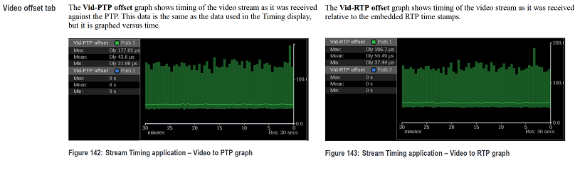 The PRISM is able to show both packet arrival times and RTP to PTP offsets. Unfortunately the latter screen is not viewable by default and requires expanding the tile to see. This means that many operators see the packet arrival time looking reasonable and then think everything is fine. It is important to expand the tile to see both screens.
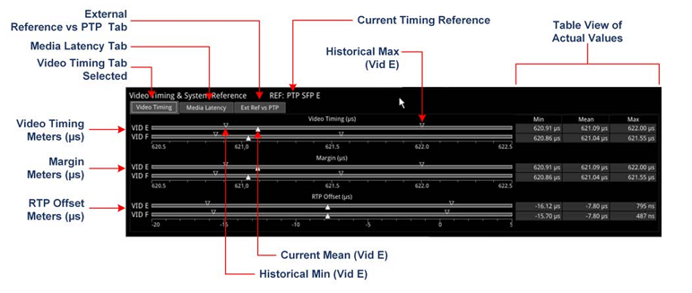 Phabrix also has two sets of “Video timing meters” which are important to check. Note that not all devices have this, the licence PHQXO-IP-MEAS is needed.
Even when looking at these analysers it’s important to remember that RTP/PTP issues can be transient (appear and disappear later). Analysing transient issues can be challenging on traditional measurement scopes designed to emulate a waveform monitor. This is why we Open Sourced our ptpmeasure tool, to allow for measurements over long periods of time without the need for large packet captures.
How a Receiver Should Use Timestamps
When receiving a timestamp, it’s not enough to simply use the packet arrival time. The receiver must also calculate an absolute timestamp, realigning the received RTP timestamp with the current PTP time (i.e removing the wraparound). To do this, when the receiver gets a timestamp, it counts how many RTP wraparounds have occurred from the start of the PTP epoch (January 1, 1970) to the current PTP time.
While this process is possible using modulo arithmetic, it can become problematic if the timestamps are too far in the future or in the past (i.e. faulty timestamps cause a gap of 13 hours or more for video, so that the number of wraparounds of the timestamp value stored does not correspond to the number of wraparounds when it was received).
Once it has calculated the absolute time, it can then synchronise video and audio and proceed with downstream processing.
However, not all receivers do this. They continue happily with illegal streams. In fact, it’s even possible to send artificial streams with bad timestamps, and the decode process works, so many receivers are not using timestamps – instead they are using packet arrival times. These devices are not compliant with ST-2110. Unfortunately bad RTP timestamps are common in many facilities and often devices (like ours) with compliant PTP/RTP implementations are blamed for problems.
What causes bad timestamps?
Things can go wrong either from the source or due to the encapsulator.
-
- Bad Sources (on encapsulator without frame sync)
If an SDI source is not locked to PTP, it may create problems. When it’s routed to the encapsulator, this can lead to incorrect or jittery packet arrival times if the encapsulator lacks a frame sync. The solution is to use a genlocked source and, if available on the encapsulator, enable frame sync.
-
- Bad Encapsulator
Sometimes, it’s the encapsulator that produces invalid RTP timestamps – for example, with a fixed offset or sudden jumps in timestamp values. To address this, it’s important to investigate whether the issue is transient (which might be resolved by rebooting the device) or an inherent problem with the product itself. It could simply be a case of the device taking a while to settle to valid RTP timestamps. Many of these issues can be challenging to explain to vendors because they lack an understanding of the difference between first packet arrival times and timestamps. Consider showing them this blog post.
We have several devices in our lab which output bad timestamps even several years after reporting the bug to that vendor.
Some Examples
Using our ptpmeasure tool, here are some real examples of some good, ok and bad sources. You can see how the arrival times are all fine, but the RTP-PTP offset can vary drastically. A lot of equipment will ignore the RTP timestamp on the bad sources as they are using packet arrival times instead.
Good
2025-09-21 23:20:17+0100: First Packet arrived 0.727 ms after ideal, RTP-PTP offset 0.000us (0 rtp). (Packet arrival GOOD, RTP Timestamp GOOD)
2025-09-21 23:20:17+0100: First Packet arrived 0.744 ms after ideal, RTP-PTP offset 0.000us (0 rtp). (Packet arrival GOOD, RTP Timestamp GOOD)
2025-09-21 23:20:17+0100: First Packet arrived 0.727 ms after ideal, RTP-PTP offset 0.000us (0 rtp). (Packet arrival GOOD, RTP Timestamp GOOD)
Ok
2025-09-21 23:20:17+0100: First Packet arrived 0.727 ms after ideal, RTP-PTP offset -11.111us (-1 rtp). (Packet arrival GOOD, RTP Timestamp OK)
2025-09-21 23:20:17+0100: First Packet arrived 0.744 ms after ideal, RTP-PTP offset -11.111us (-1 rtp). (Packet arrival GOOD, RTP Timestamp OK)
2025-09-21 23:20:17+0100: First Packet arrived 0.727 ms after ideal, RTP-PTP offset -11.111us (-1 rtp). (Packet arrival GOOD, RTP Timestamp OK)
Bad
2025-09-21 23:22:53+0100: First Packet arrived 0.744 ms after ideal, RTP-PTP offset -6655.556us (-599 rtp). (Packet arrival GOOD, RTP Timestamp BAD)
2025-09-21 23:22:53+0100: First Packet arrived 0.727 ms after ideal, RTP-PTP offset -6655.556us (-599 rtp). (Packet arrival GOOD, RTP Timestamp BAD)
2025-09-21 23:22:53+0100: First Packet arrived 0.744 ms after ideal, RTP-PTP offset -6655.556us (-599 rtp). (Packet arrival GOOD, RTP Timestamp BAD)
Wrapping Up: What You Need to Know
To troubleshoot issues effectively, it’s crucial to understand the difference between timestamps and packet arrival times, regularly measure and monitor timestamps, ensure encapsulators have genlocked sources or frame sync capabilities, and identify the devices creating invalid timestamps.
Timestamps are a vital component of the ST 2110 standard, enabling receivers to synchronise audio and video streams effectively.
We have led the way for nearly a decade in high-performance, software based ST-2110 technology up to 100 Gigabit. Learn more about our low-latency encoders and decoders.